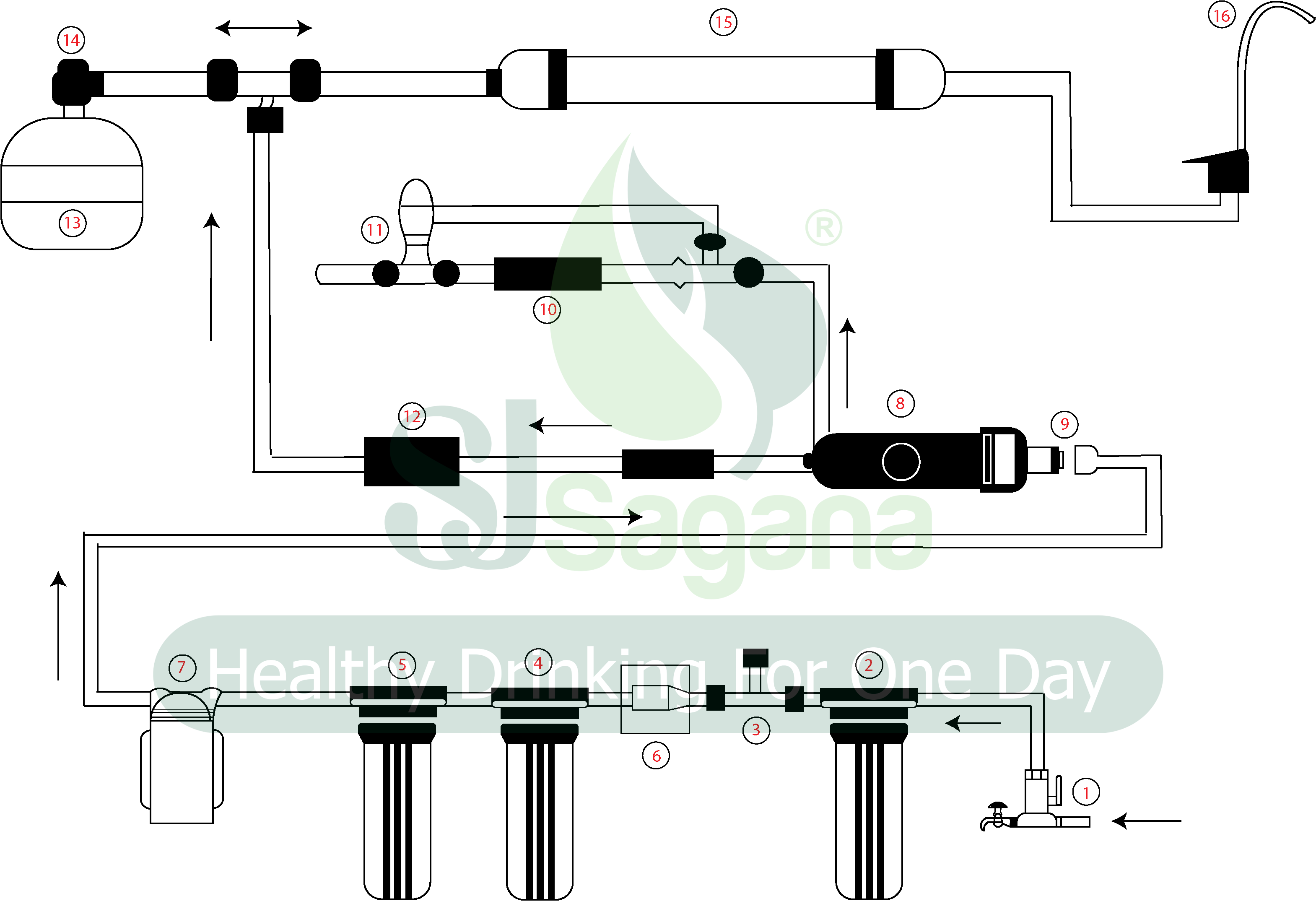
Operational Cycle Diagram
- 3-way valve
- PP filter
- Low pressure (No water source, the machine does not operate)
- Granular activated carbon filter (UDF)
- Compressed activated carbon filter (CTO)
- Solenoid valve (No water flow when the machine is not operating)
- Pressure pump
- R.O housing
- R.O membrane
- Regulating valve
- Horizontal valve
- High pressure (Automatically shuts off when the tank is full)
- Pressure tank
- Vertical valve
- Activated carbon filter (T-33)
- Water faucet
Notes:
– Installation and usage must follow the instructions of the technical staff.
– After installation, customers should flush out 10 liters of water before use to clean any dirt accumulated during installation.
– If there are air bubbles in the water on the first day of use, it is a normal physical phenomenon and does not affect health. This phenomenon will disappear after a few days of use.


 Tiếng Việt

